Rebar cage visualization package
📦 DELIVERABLES COMPLETE
✅ Individual Rebar Type Images (12 types)
All bar types include:
- 3D bent shape visualization
- Dimensional callouts (length, bends, hooks)
- Quantity required
- Location/purpose annotations
- Detailed bending specifications
R1 - Base Slab Longitudinal Bars
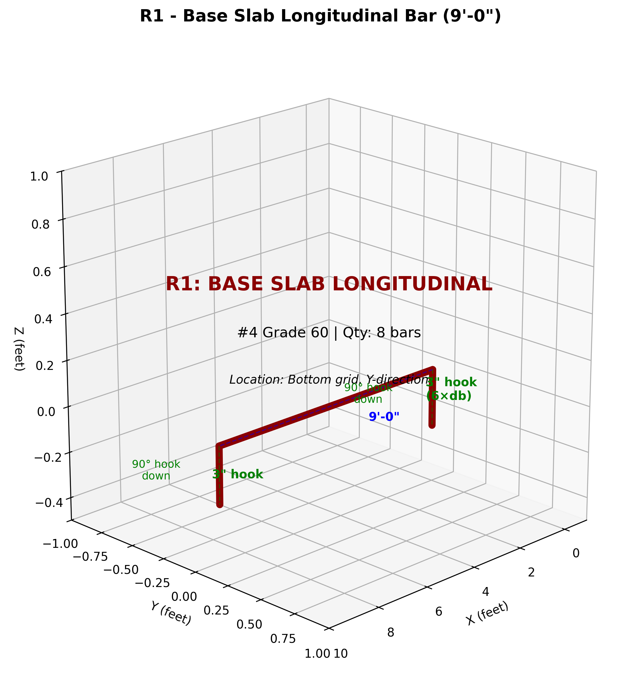
Specifications:
- Length: 9’-0” (8’ + 6” hooks both ends)
- Quantity: 8 bars
- Bends: 90° hooks both ends, pointing down
- Hook extension: 3” (6×db)
- Location: Bottom grid, Y-direction (along 8’ length)
- Spacing: 12” on center
R2 - Base Slab Transverse Bars
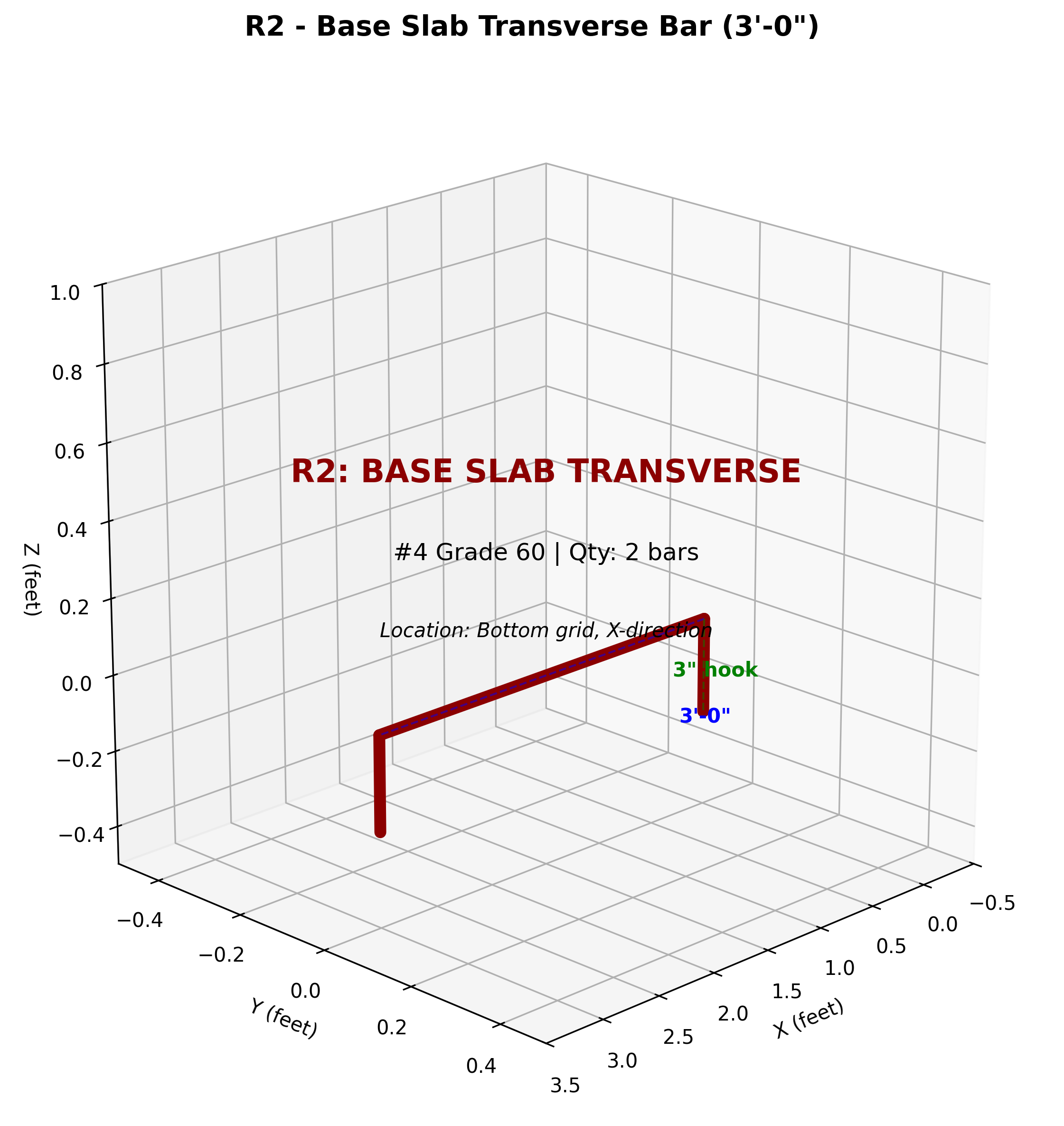
Specifications:
- Length: 3’-0” (2’ + 6” hooks both ends)
- Quantity: 2 bars
- Bends: 90° hooks both ends, pointing down
- Location: Bottom grid, X-direction (across 2’ depth)
R3 - Seat Wall Verticals
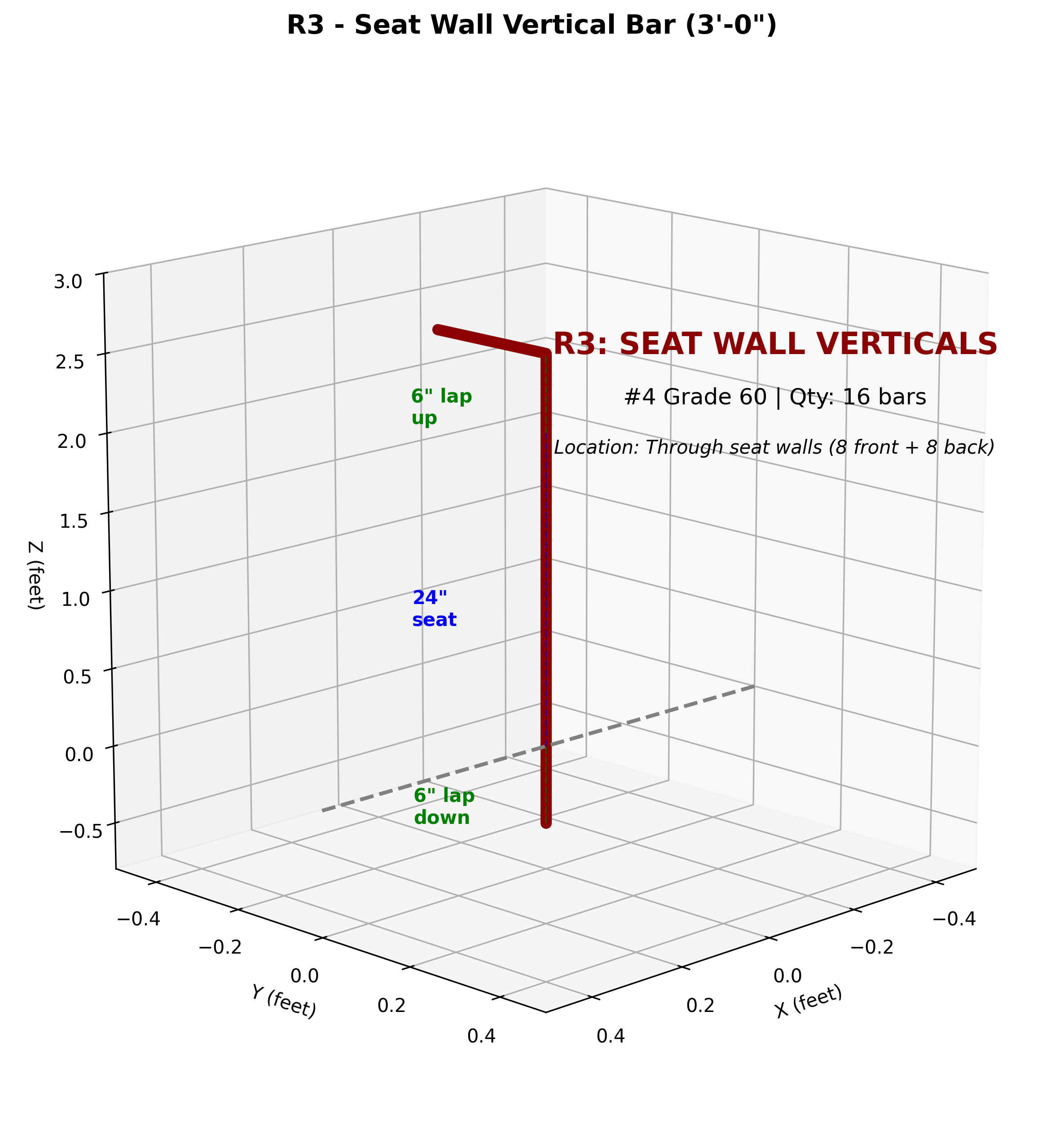
Specifications:
- Length: 3’-0” (6” lap down + 24” seat + 6” lap up)
- Quantity: 16 bars (8 front face + 8 back face)
- Bends: 90° hook at top with 6” lap
- Location: Vertical through seat walls (24” tall section)
- Critical: These connect base to parapets - proper lapping essential
R4 - Seat Wall Horizontal Ties
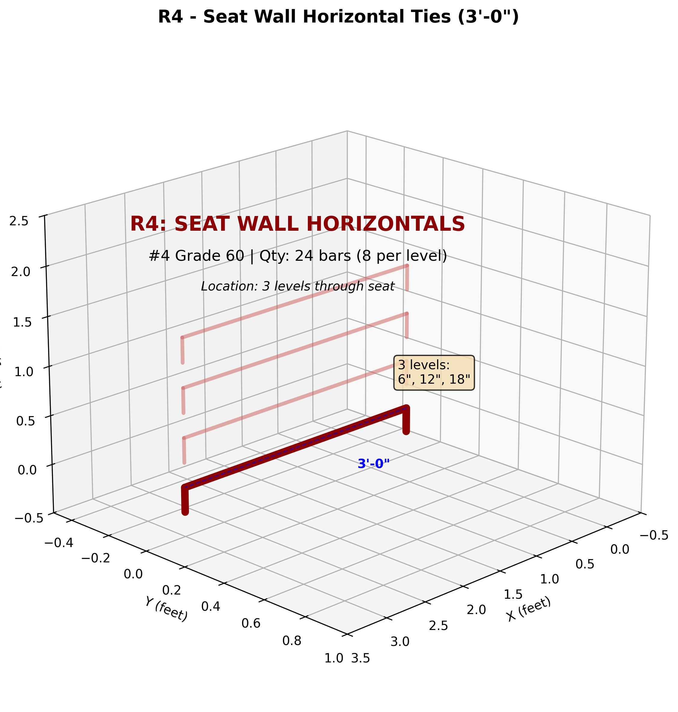
Specifications:
- Length: 3’-0” (2’ depth + 6” hooks)
- Quantity: 24 bars (8 bars × 3 levels)
- Bends: 90° hooks both ends
- Levels: 6”, 12”, 18” above base (3 levels through seat)
- Location: Horizontal ties connecting front/back verticals
R5 - Back Parapet Verticals

Specifications:
- Length: 2’-0” (6” lap + 12” parapet + hook)
- Quantity: 8 bars
- Bends: 90° hook at top
- Location: Back parapet (approach side), laps onto R3 verticals
- Height: Extends from 24” (top of seat) to 36” (final height)
R6 - Side Parapet Verticals (Arm Rests)
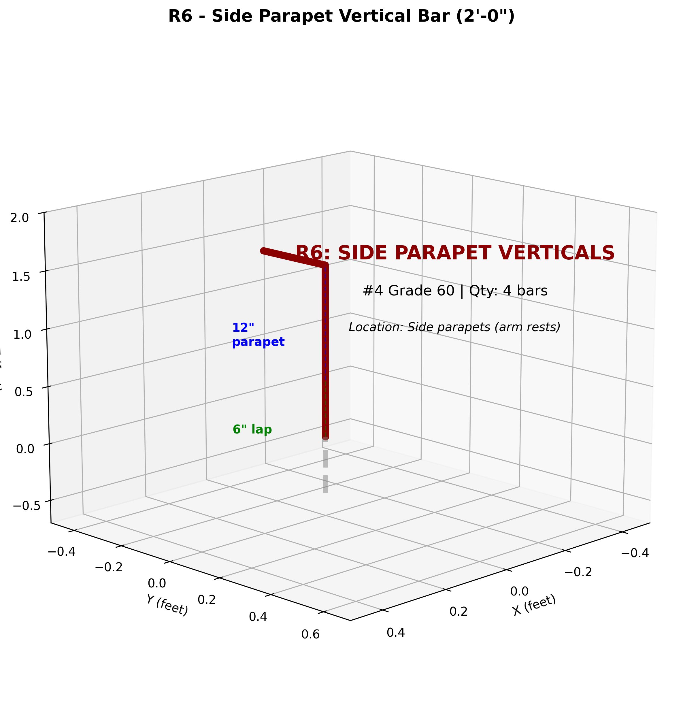
Specifications:
- Length: 2’-0” (same as R5)
- Quantity: 4 bars (2 per end)
- Bends: 90° hook at top
- Location: Side parapets at Y = ±48” (both ends)
- Purpose: Forms “arm rests” at edges
R7 - Bearing Plate Stirrups
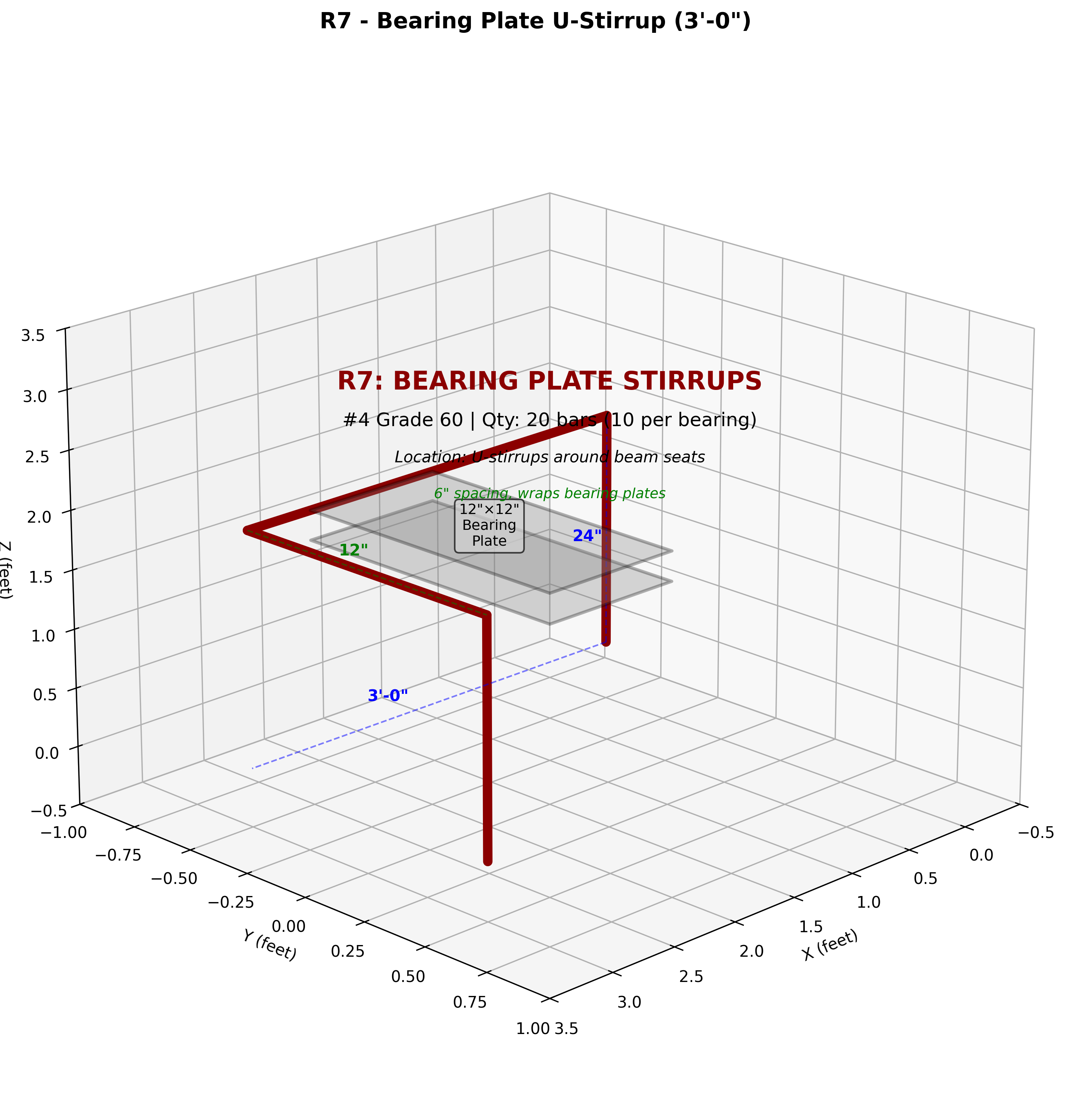
Specifications:
- Length: 3’-0” (U-shaped stirrup)
- Quantity: 20 bars (10 per bearing location)
- Bends: U-shape with 90° bends at top corners
- Spacing: 6” intervals around bearing plates
- Location: Y = ±30” (2 bearing plate locations)
- Critical: Extra reinforcement for beam load transfer
R8 - Corner Diagonal Reinforcement
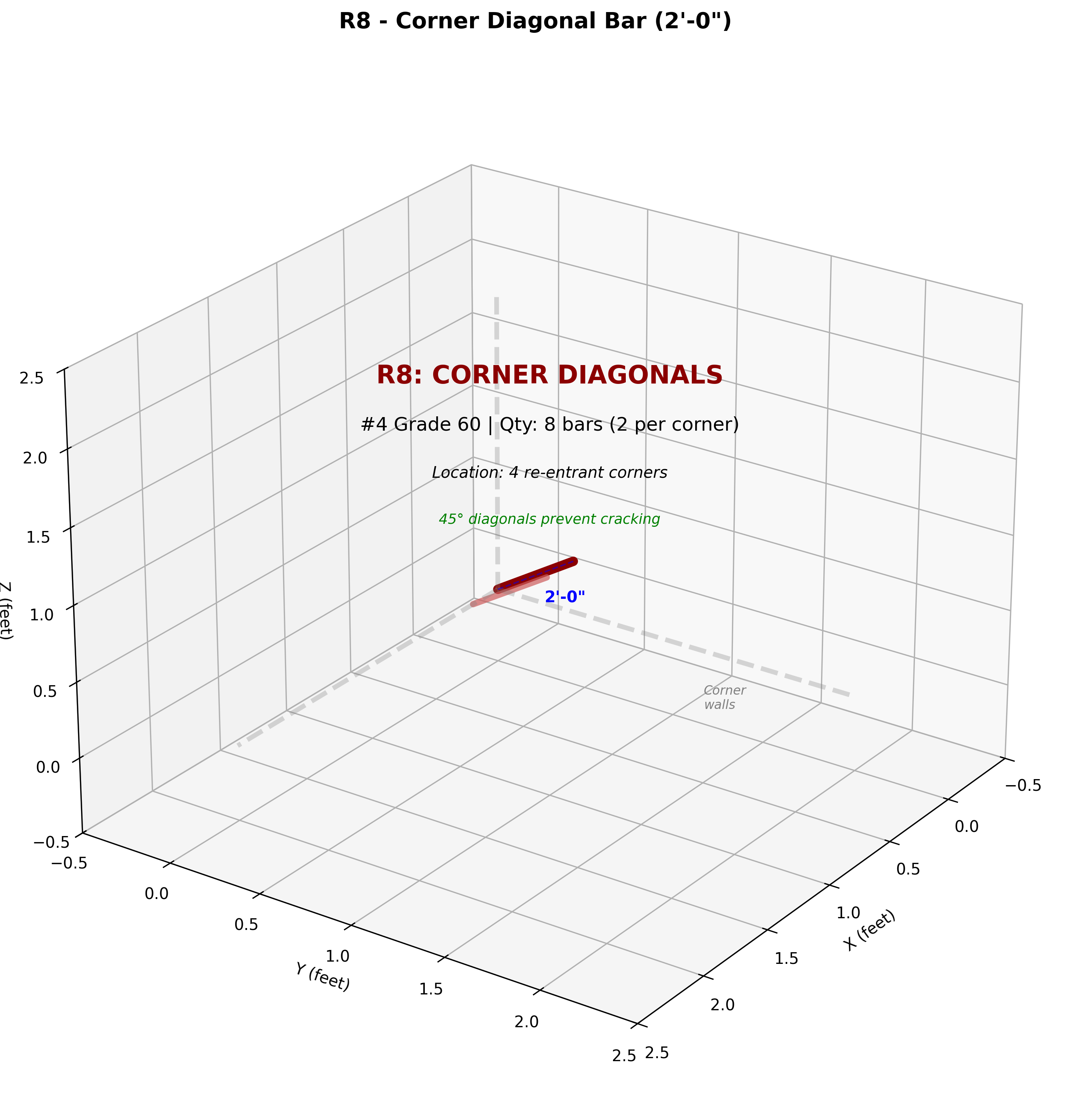
Specifications:
- Length: 2’-0” (straight diagonal)
- Quantity: 8 bars (2 per corner)
- Bends: None (straight bars at 45° angle)
- Location: 4 re-entrant corners where walls meet
- Purpose: Prevents cracking at stress concentrations
R9 - Wing Wall Verticals
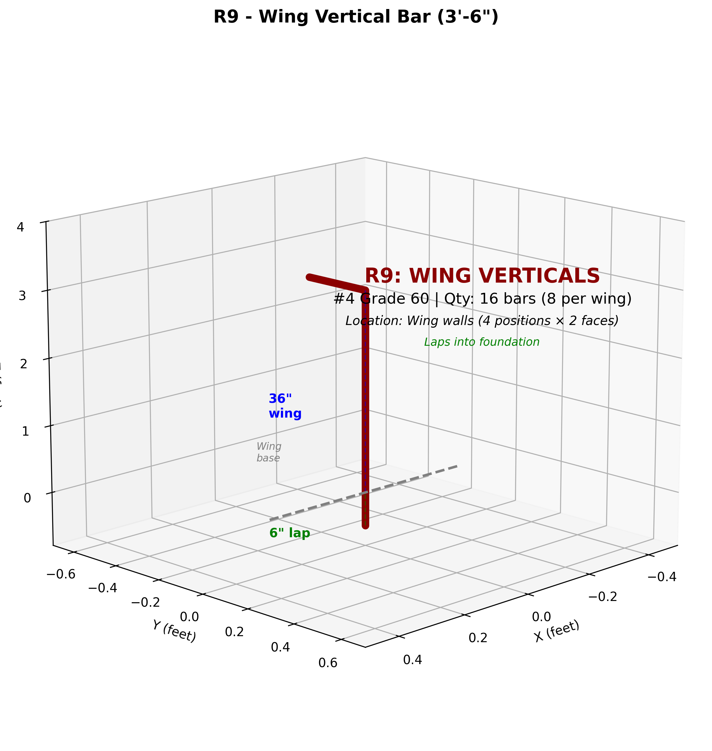
Specifications:
- Length: 3’-6” (6” lap + 36” wing height)
- Quantity: 16 bars (8 per wing = 4 positions × 2 faces)
- Bends: 90° hook at top
- Location: Wing walls (both at 29° angle)
- Spacing: 4 positions along 4.33’ wing extension
R10 - Wing Horizontal Ties
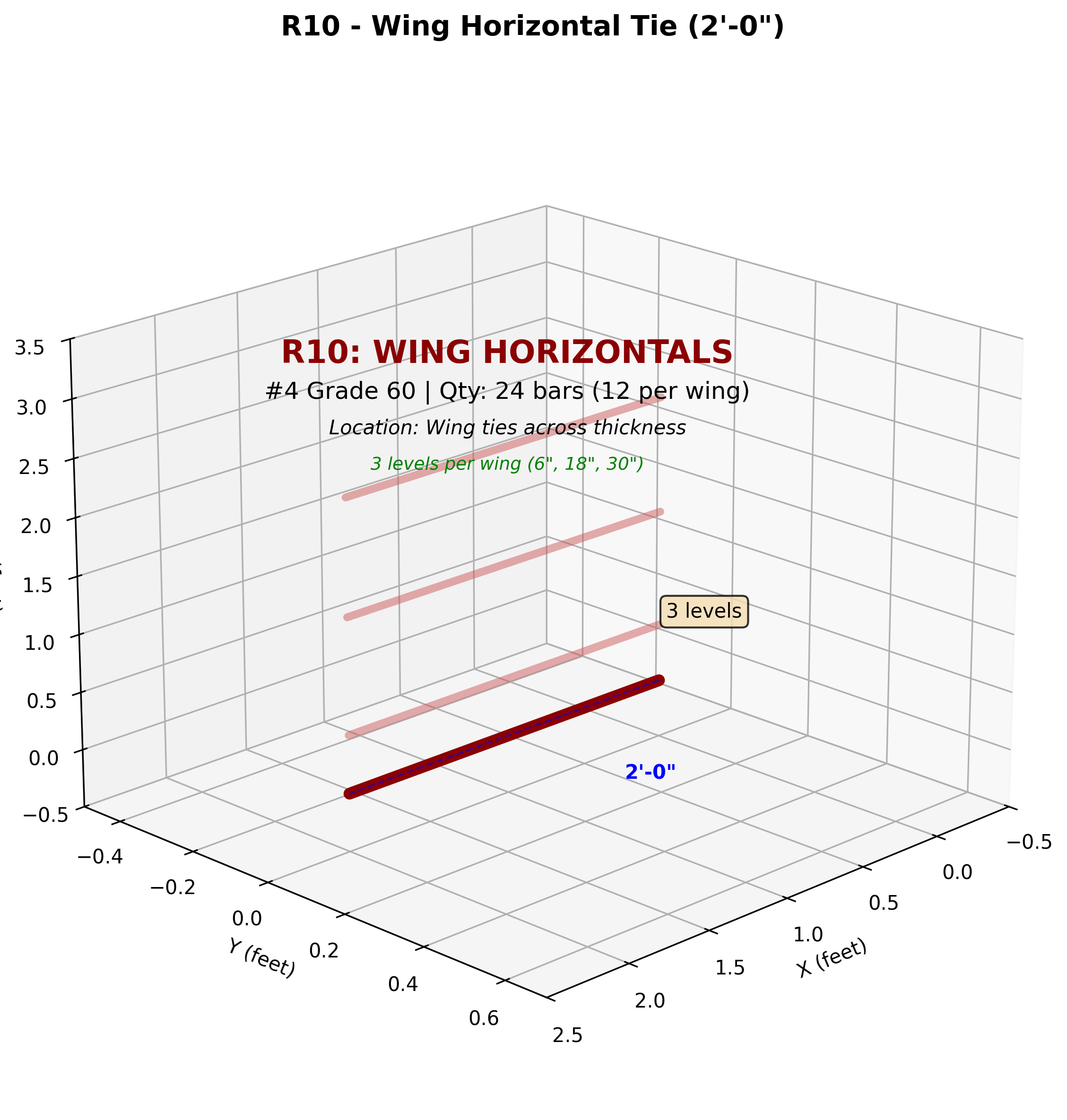
Specifications:
- Length: 2’-0” (straight, spans wing thickness)
- Quantity: 24 bars (12 per wing = 4 positions × 3 levels)
- Bends: None (straight bars)
- Levels: 6”, 18”, 30” above base (3 levels per wing)
- Purpose: Connects wing verticals, provides lateral stability
R11 - Expansion Joint Dowels ⚠️ SPECIAL
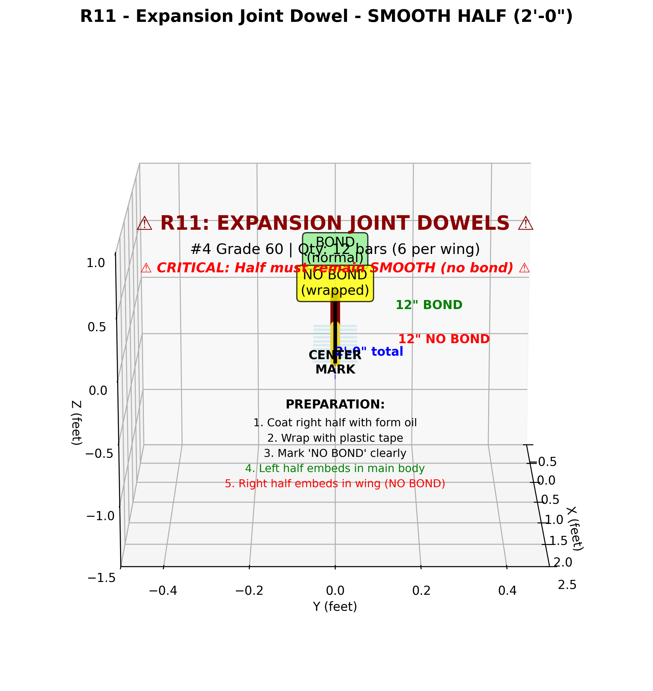
Specifications:
- Length: 2’-0” (half bonded, half smooth)
- Quantity: 12 bars (6 per wing)
- Bends: None (straight bars)
- ⚠️ CRITICAL TREATMENT:
- Left half (12”): Normal bond - embeds in main body
- Right half (12”): NO BOND - wrapped in plastic, embeds in wing
- Preparation: Coat with form oil, wrap with plastic tape
- Purpose: Allows wing to settle independently while providing shear resistance
R12 - Drainage Pipe Cages
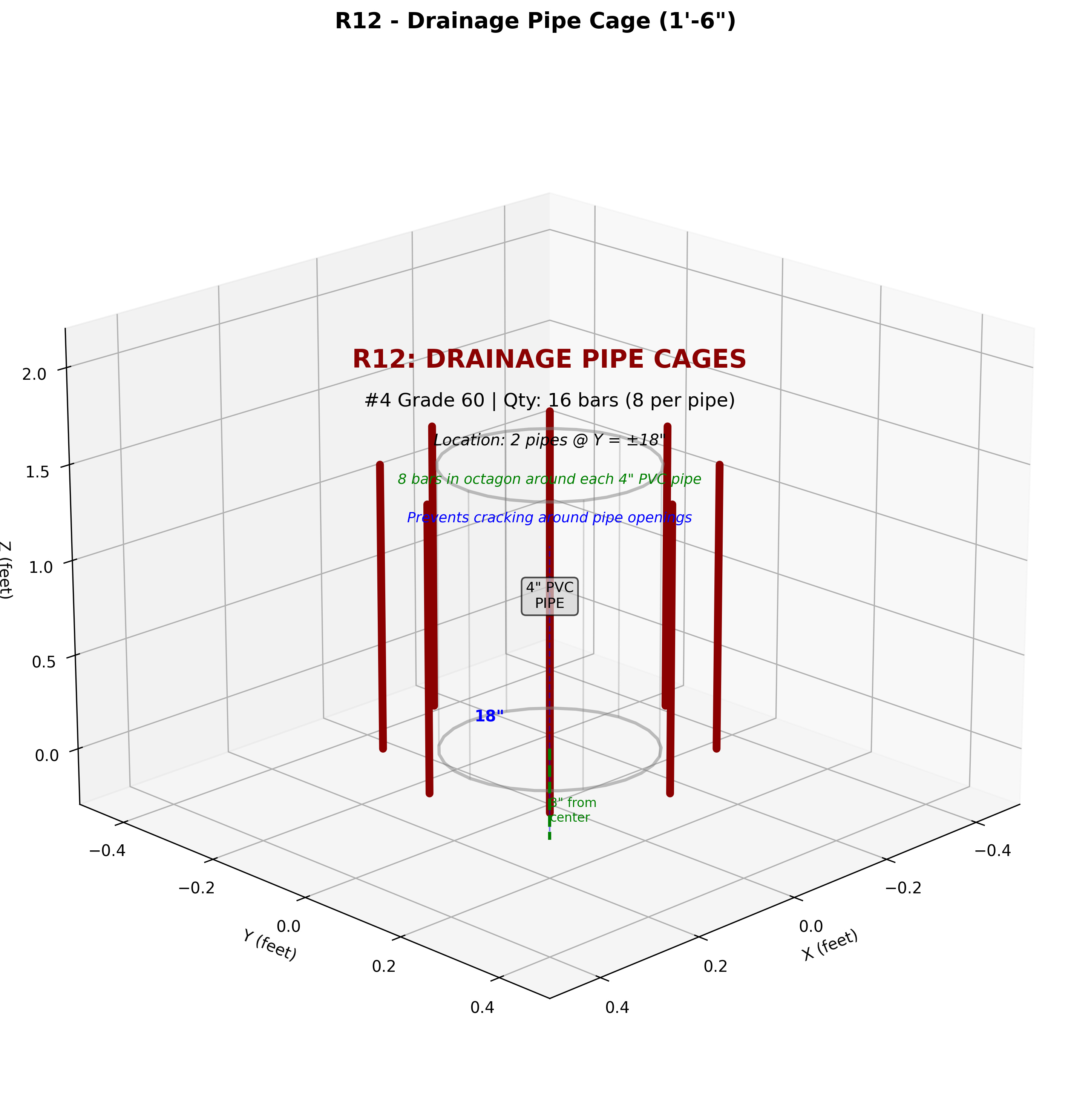
Specifications:
- Length: 1’-6” (straight bars)
- Quantity: 16 bars (8 per pipe = 2 pipes)
- Bends: None (straight bars parallel to pipe)
- Pattern: Octagonal cage around 4” PVC pipe
- Location: Y = ±18” (two drain pipes)
- Purpose: Reinforces concrete around pipe openings, prevents cracking
🏗️ COMPLETE ASSEMBLY VIEWS
Complete Rebar Cage Assembly - Isometric View
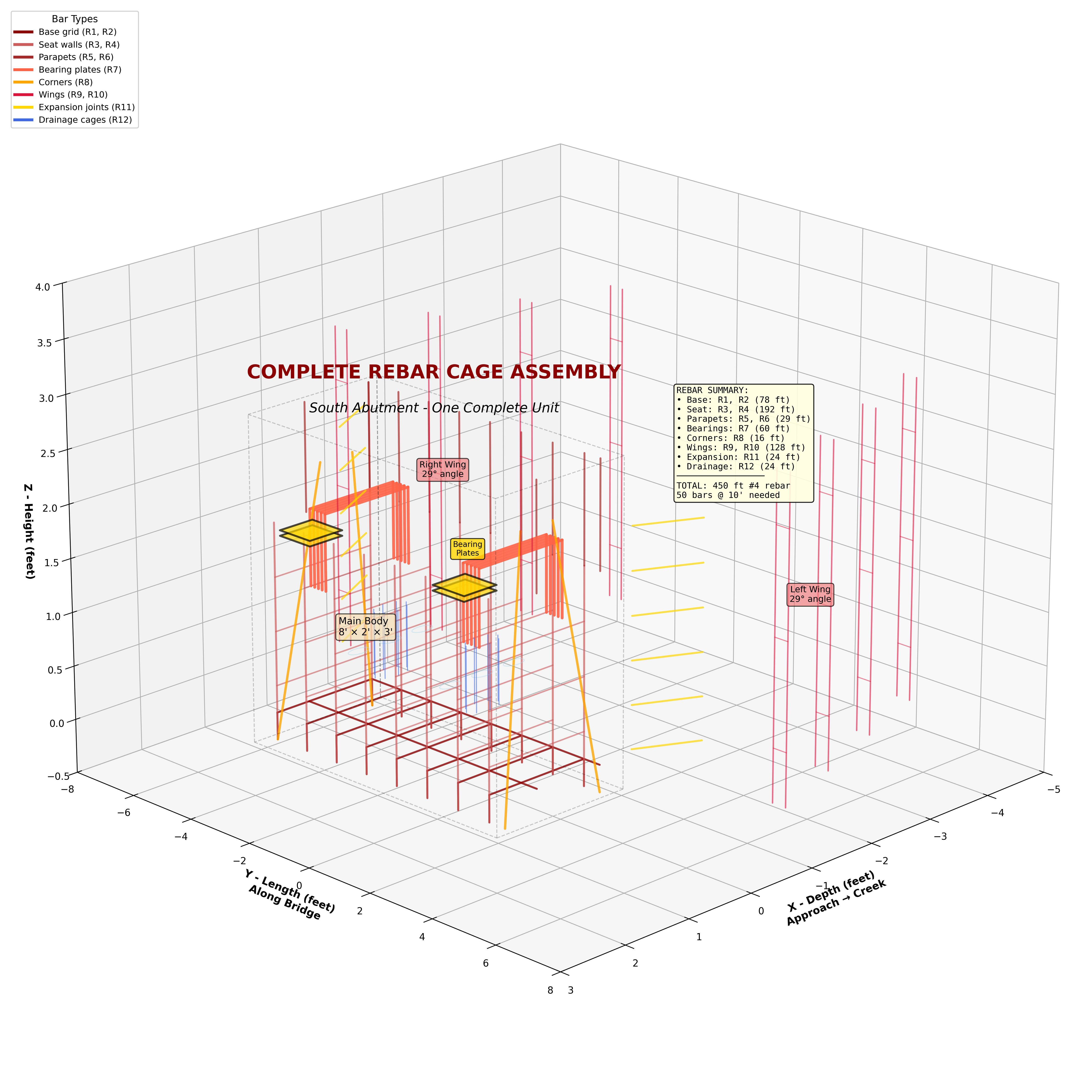
Shows:
- All 12 bar types integrated
- Main body (8’ × 2’ × 3’)
- Both wing walls (29° angles)
- Bearing plate locations (marked in gold)
- Drainage pipes (light blue)
- Expansion joints (gold bars)
- Color-coded legend for all bar types
- Rebar summary statistics
- Component labels
Key Features Visible:
- ✓ Base grid (R1, R2) in dark red
- ✓ Seat walls (R3, R4) in lighter red
- ✓ Parapets (R5, R6) in brown
- ✓ Bearing plates (R7) in tomato red with gold plates
- ✓ Corner reinforcement (R8) in orange
- ✓ Wing walls (R9, R10) in crimson
- ✓ Expansion joints (R11) in gold
- ✓ Drainage cages (R12) in royal blue
Complete Cage - Top View
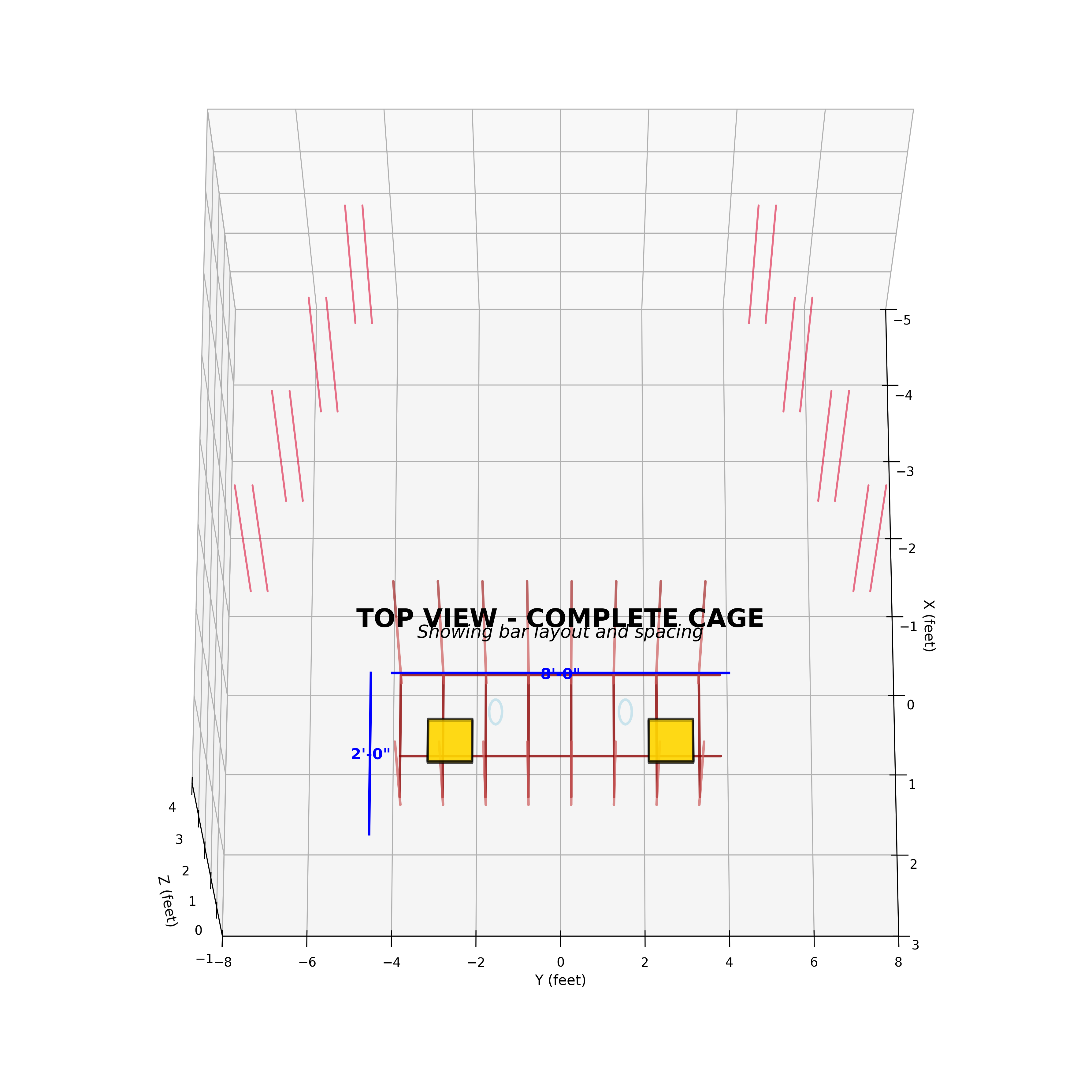
Shows:
- Bar layout and spacing from above
- Wing angles clearly visible (29°)
- Bearing plate positions (Y = ±30”)
- Drainage pipe locations (Y = ±18”)
- 12” spacing pattern throughout
- Overall dimensions (8’ × 2’ main body)
Best for:
- Understanding bar spacing
- Verifying layout dimensions
- Planning formwork
- Inspector review
📏 SPECIFICATIONS SUMMARY
Complete One Abutment
| Component | Rebar (ft) | Bar Types | Bar Count |
|---|---|---|---|
| Base Slab | 78.0 | R1, R2 | 10 |
| Seat Walls | 192.0 | R3, R4 | 40 |
| Parapets | 28.8 | R5, R6 | 12 |
| Bearing Plates | 60.0 | R7 | 20 |
| Corners | 16.0 | R8 | 8 |
| Wings (both) | 128.0 | R9, R10, R11 | 52 |
| Drainage | 24.0 | R12 | 16 |
| TOTAL | 450.0 ft | All 12 types | ~158 pieces |
Materials Needed
- #4 Grade 60 Rebar: 50 bars @ 10’ = 500 linear feet
- Concrete Cover: 3” all faces (ACI 318-19)
- Spacing: 12” on center throughout
- Lap Splices: 24” minimum (40×db)
- Hooks: 90° standard with 3” extension (6×db)
🎨 COLOR CODING SYSTEM
Images use consistent color coding:
| Color | Component | Bar Types |
|---|---|---|
| Dark Red (#8B0000) | Base grid | R1, R2 |
| Light Coral (#CD5C5C) | Seat walls | R3, R4 |
| Brown (#A52A2A) | Parapets | R5, R6 |
| Tomato (#FF6347) | Bearing reinforcement | R7 |
| Orange (#FFA500) | Corner diagonals | R8 |
| Crimson (#DC143C) | Wing walls | R9, R10 |
| Gold (#FFD700) | Expansion joints | R11 (special) |
| Royal Blue (#4169E1) | Drainage cages | R12 |
| Gold blocks | Bearing plates | 12”×12” steel |
| Light blue | PVC pipes | 4” drainage |
| Gray dashed | Form outlines | Reference only |